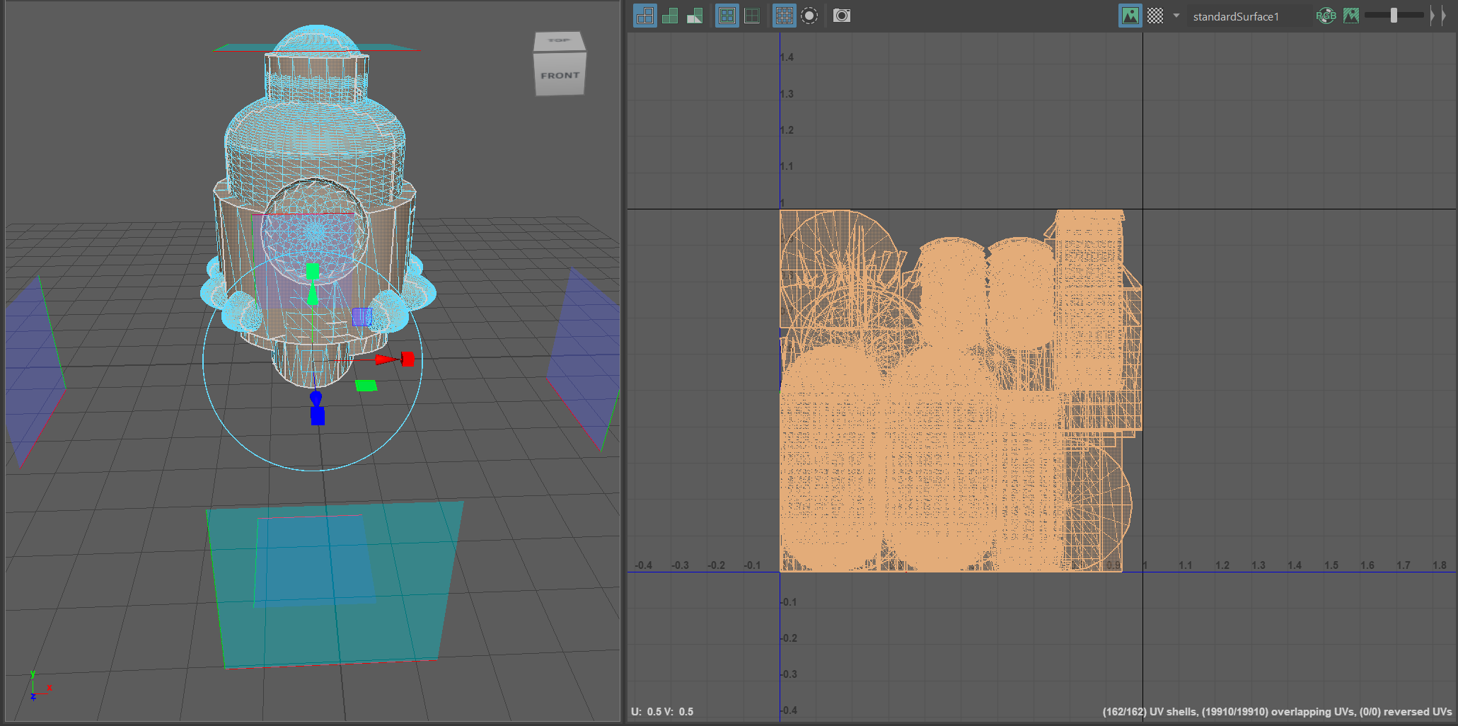
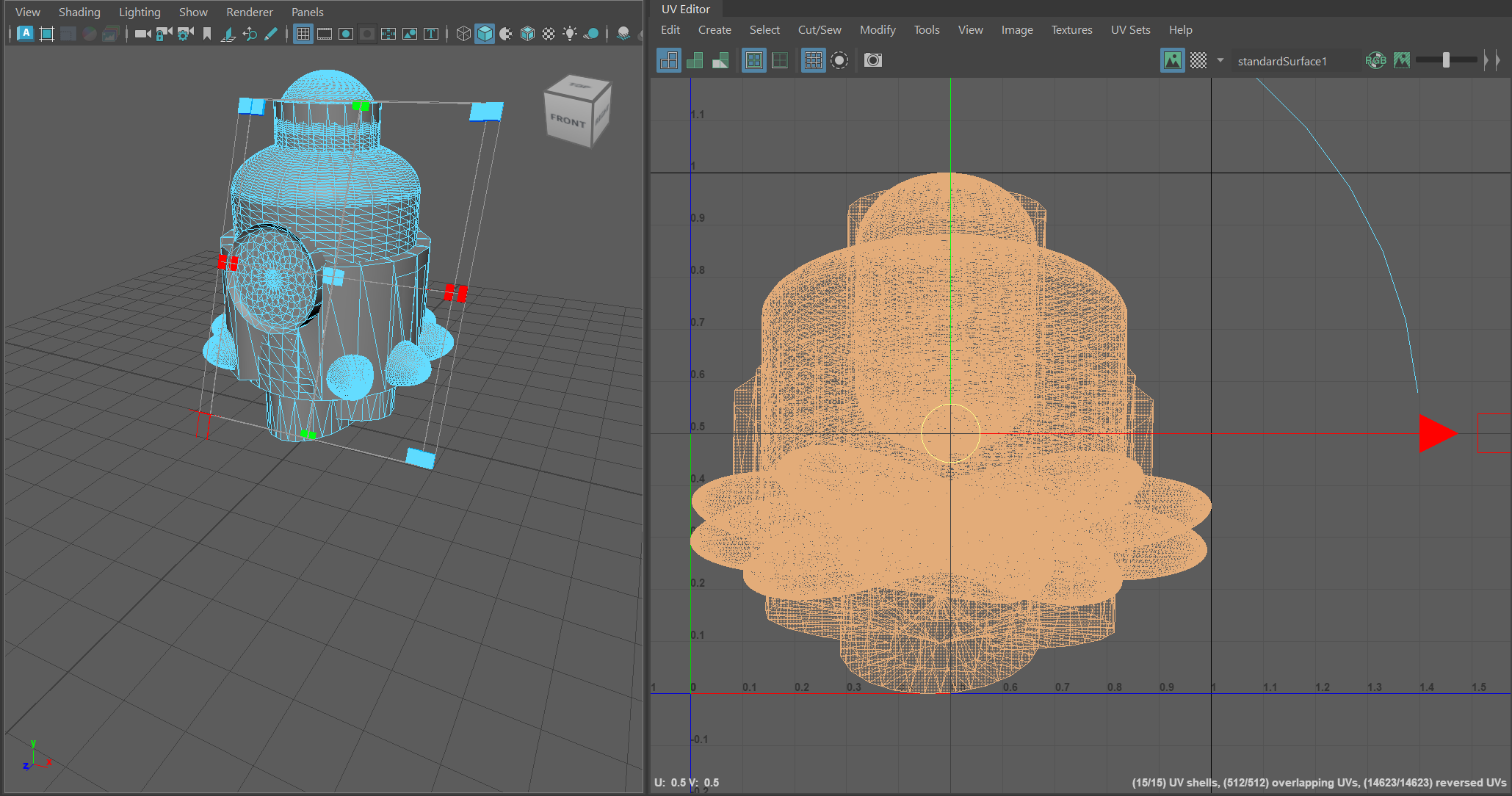
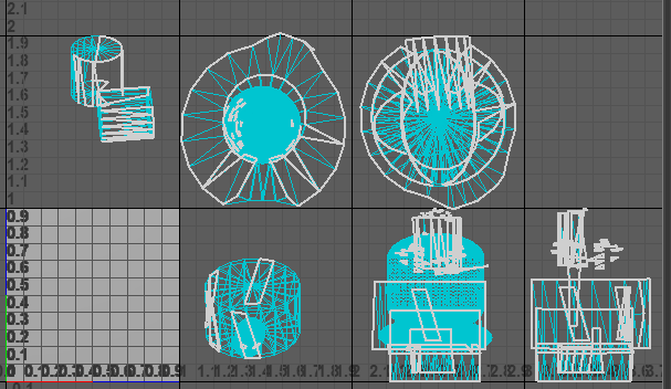
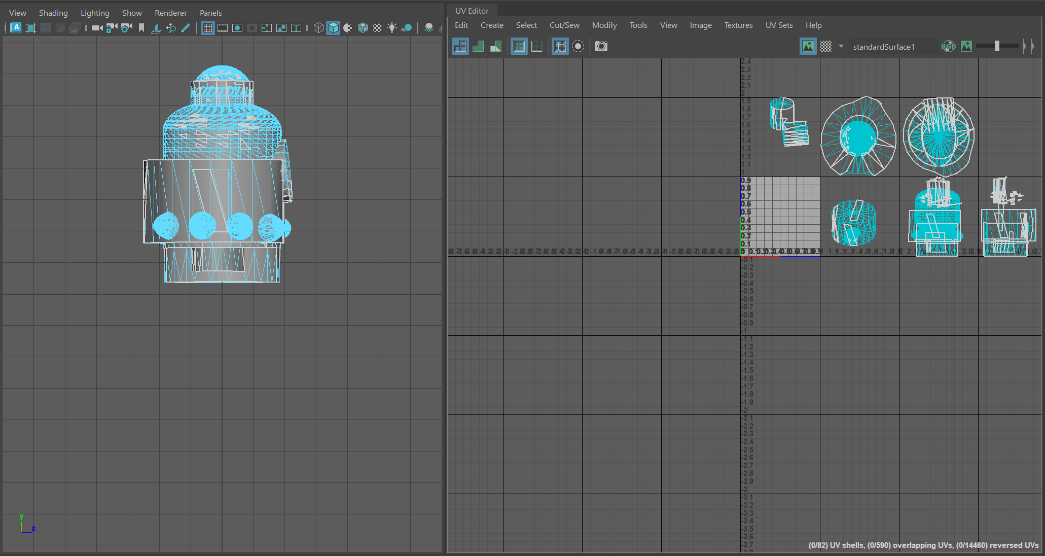
An UV unwrapping procedure was required to be done shortly after finished moderating. Why is UV unwrapping crucial? When using Adobe Substance Painter, UV unwrapping enables more precise texture and colour filling. The first step in unwrapping is switching the mode from General to UV, which will alter the workspace for the necessary operation. Each section is separately released from orthographic and perspective projections, such as top, right, left, and bottom, while utilising the Face mode. To accurately depict each side of the projection, the UV graph was used to plan and move each projection. It was exported as an FBK file and opened in Adobe Substance Painter after the pod had been successfully unwrapped.
Adobe Substance Painter
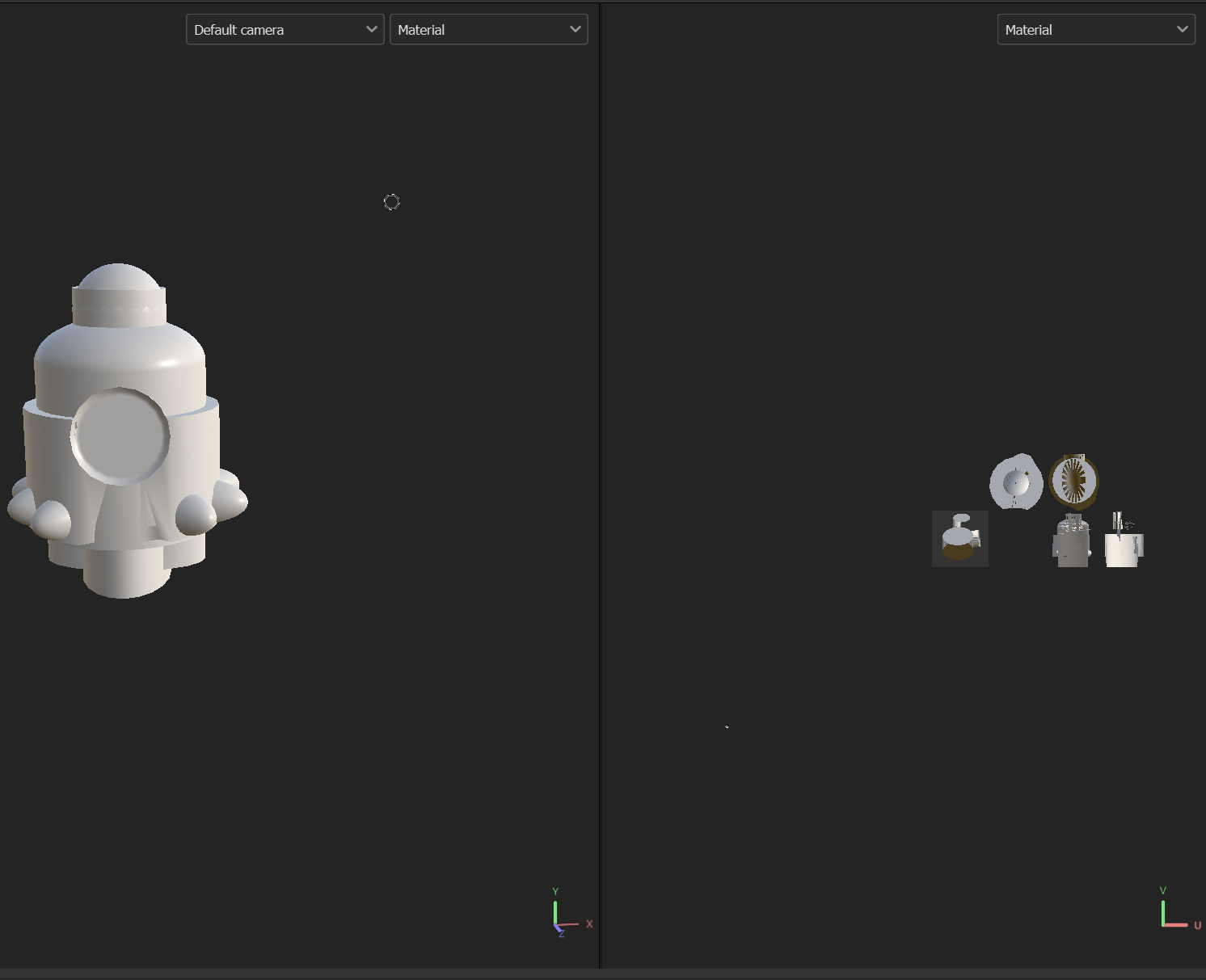
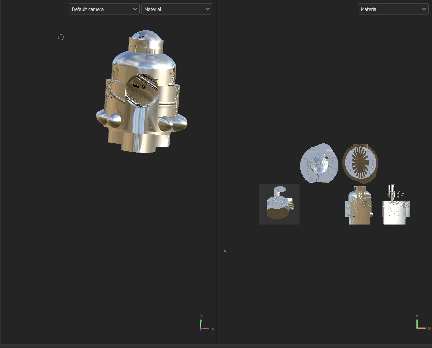
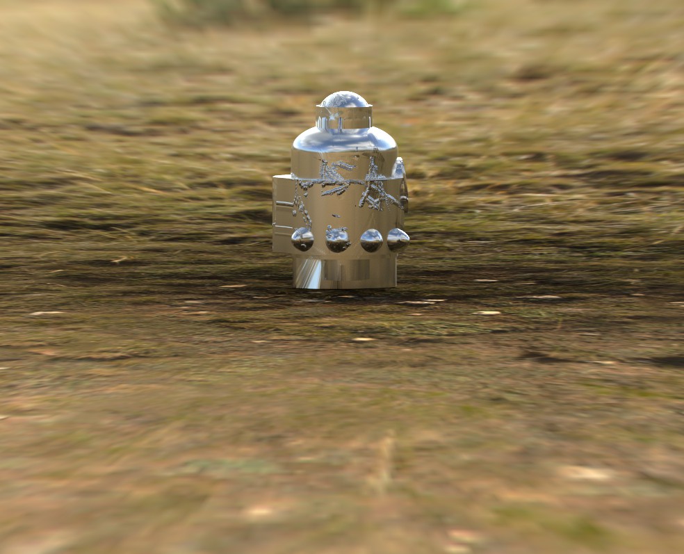
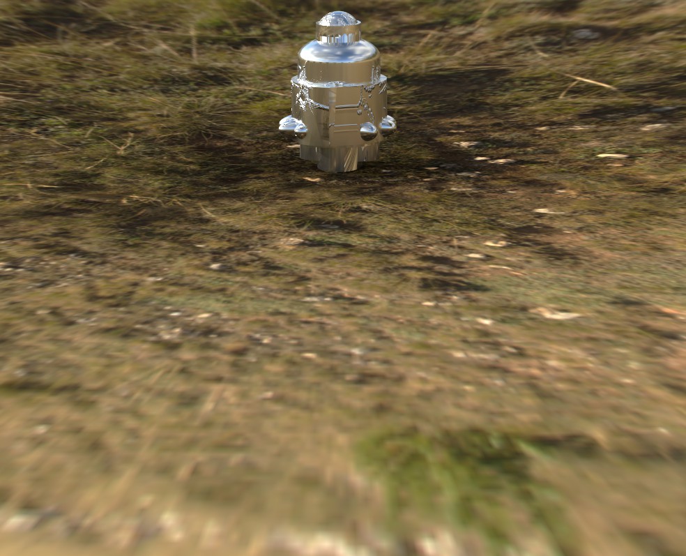
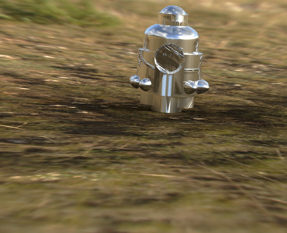
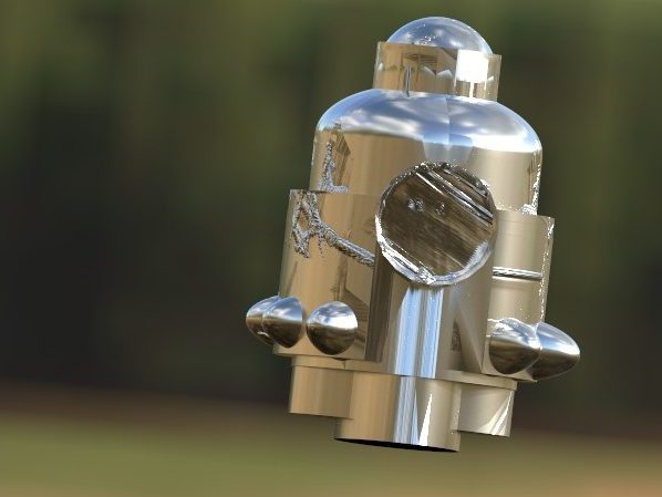
The workspace had two areas when the file was opened: one for the model and one for the UV. Because I experimented with several textures and brushes during the colouring process and made a small error when applying the UV, the textures produced intriguing and realistic results. To accomplish smooth painting of the surface, the decision was made to colour in the UV. which wasn’t successful because the brush was only drawing lines. So, a small adjustment was made to the brush parameters. After varying, the brush created a bright metallic surface with intriguing rust that may have the appearance of veins. The textures were successfully sent back to Maya after the painter process, and rendering got going.
Rendering